RS-232 Sensor Integration Guide
Unlike analog auxiliary sensors, instruments that output serial RS-232 data are more challenging to integrate with Sea-Bird Scientific CTDs. Despite RS-232 being a standard communication protocol, most instruments have a unique data output format and command set. As such, getting two instruments to communicate in a way that is understandable to one another requires specific configuration, especially when the two instruments are from different manufacturers.
That said, if you can work through the integration then RS-232 output sensors can report significantly more information than an analog sensor’s 0-5 V signal. These instruments may be capable of measuring multiple parameters in a single package (as is the case with the ECO-Triplet) or may report diagnostic data for QA/QC and troubleshooting purposes.
Four Sea-Bird Scientific CTDs can support serial RS-232 sensors to varying degrees: the 9plus, 19plus V2, 16plus V2, and 25plus. This guide covers how to configure these CTDs to accept auxiliary RS-232 data. Note: The RS-232 device itself will likely require configuration to work with the CTD – refer to the instrument’s manual for more information.
19plusV2 / 16plusV2
Both the 19plus V2 and the 16plus V2, can support a limited set of serial RS-232 sensors. For the CTD to communicate with the sensor, both instrument’s baud rates must match (the default baud rate for the CTD is 9600, and can be changed with the command “BaudRate=X), where X = 600, 1200, 2400, 4800, 9600, 19200, 38400, 57600, or 115200.
The following sensors are compatible with these CTDs, and are activated by a single command:
- SBE 63 optical dissolved oxygen sensor (SBE63=Y)
- SBE 38 secondary temperature sensor (SBE38=Y)
- Single, dual, or triple channel ECO sensor (WetLabs=Y)
- WETStar flow-through fluorometer (WetLabs=Y)
- C-Star (WetLabs=Y)
- SeaOWL UV-A™ (WetLabs=Y)
- Pro-Oceanus Gas Tension Devices (GTD=Y, or DualGTD=Y for two Gas Tension Devices)
- Aanderaa Optode 4330 or 4835 (Optode=Y)When configured to accept these sensors
- SBE 50 pressure sensor (SBE50=Y, SBE 16plus V2 only)
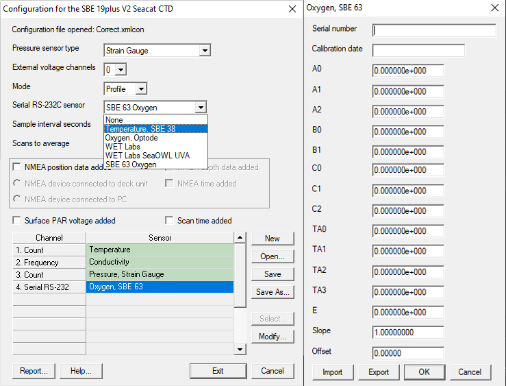
Once connected and configured, the RS-232 sensor’s output will be integrated in the CTD’s data stream as hexadecimal data. To properly convert this data, add the RS-232 sensor to the CTD’s .xmlcon file:
- Click on the dropdown arrow next to “Serial RS-232C sensor”
- Select the appropriate sensor
- Double click on the sensor in the table in the bottom (Oxygen, SBE 63 in the figure below)
- Add the calibration coefficients for this sensor
- Save the .xmlcon file
To communicate with the RS-232 device, users can send the command “gatewayserial” to the CTD to send commands to the RS-232 device instead of the CTD. To resume communication with the CTD, send “Ctrl Shift X”.
25plus
A more flexible option, the SBE 25plus profiling CTD is customizable for wider support for most serial output sensors. Equipped with two RS-232 channels, the 25plus can be extensively configured to accept most data formats and send user-defined strings to the sensor. However, data from serial-output sensors cannot be transmitted in real-time. Data from these sensors are saved in the CTD’s 2 Gb internal memory.
Configuring the SBE 25plus to log serial data requires an understanding of exactly which characters are sent and received, in what order, and when. Follow this procedure to collect the data needed to interface an unknown serial device with the 25plus.
- Activate the serial data channel on the 25plus with the command SetEnableSer#=Y, where # = 1 or 2 for serial data channels 1 or 2, respectively.
- Connect the serial sensor to the 25plus with the appropriate cable.
- Reset the serial sensor interface in the 25plus to factory settings with the InitSer# command.
- Set the serial channel’s baud rate with SetBaudSer#=. The other serial communication parameters are fixed at 8 data bits, 1 stop bit and no parity.
- If the serial instrument is externally powered, send SetVauxPower3=Y to power the connector to which the serial instrument is attached.
- After initialization (InitSer#), the execution and termination characters are both set to carriage return line feed (ASCII 254) and the prompt is set to S>. The execution character is sent at the end of a command to alert a serial device that a new command is available, while the termination character is used by the 25plus to determine if a reply is complete. The prompt is sent from the serial sensor to the 25plus to indicate that it is awake and ready to receive commands. If the execution and termination characters and prompt for the serial sensor are known, set them with SetExecCharSer#=, SetTermCharSer#=, and SetPromptSer#= respectively. The interface will seem slow if these are set incorrectly, because SetTimeoutSer#= and SetFailoutSer#= are timeouts that control how long the 25plus waits for a response and for data.
- Test your setup by sending a command to the serial sensor with the ToSer#= command (for example, ToSer1=ts sends ts to the serial sensor; if this is a command that the serial sensor recognizes, it will respond.)
For more examples and more information, download Appendix IV from the 25plus manual.
After the cast, the serial data is stored in the 25plus internal memory, either inline with the CTD data or as a separate .txt file. When stored inline, the full output string from the RS-232 sensor is printed next to the hexadecimal data in the CTD’s .xml data file
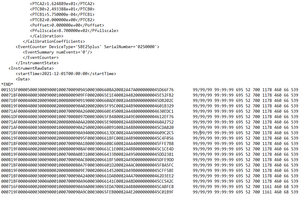
This feature is useful for aligning samples across the CTD + analog aux sensors + RS-232 aux sensors. However, if the RS-232 sensor samples faster than the 25plus’ 16 Hz, then users may opt to save RS-232 sensor data in a separate .txt file to capture the full sampling resolution.
9plus
By default, the 9plus CTD does not support auxiliary RS-232 sensors. To provide support for one RS-232 output sensor, the 9plus and 11plus V2 deck unit must have the “Serial Uplink Modification”.
With this modification, the user can send data from an underwater RS-232 instrument to the computer at 9600 baud.
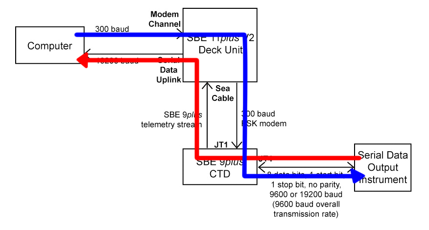
Users can also send commands to the underwater instrument via the 300 baud modem channel. This is the same channel used to send commands to the SBE 32 water sampler.
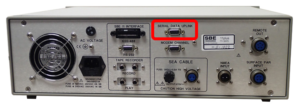
The serial uplink channel can handle RS-232 data at 9600 baud, or data transmit at 19200 baud with intervals of no data transmission (for an average transmission rate not to exceed 960 bytes/second). When connected and configured, the RS-232 data from the sensor can be captured by software via the the “Serial Data Uplink” connector on the back of the 11plus V2 deck unit. This data stream is separate from the 9plus CTD data stream.
Note: this modification creates some limitations on the CTD system:
- Once this modification is installed, sea cable length is limited to 8000 meters before communications will degrade.
- The CTD will no longer be compatible with the following:
- 11plusV2 set up for standard transmission
- Older deck units that lack the 300 baud water sampler modem channel
- The 17plus V2 SeaRAM data logger/AFM
- The G.O. 1015 water sampler
- Tape recorder interface on the 11plus V2
Related Posts


Featured Posts
Oceanology International 2024
We hope to see you at #Oi24 We are excited to return to Oceanology International 2024 again in London, UK from March 12-14. Overview Oceanology International brings together 500+ exhibitors in the only event that links the three key players in the industry:...
Ocean Sciences Meeting 2024
We hope to see you at #OSM24 We are excited to return to Ocean Sciences Meeting 2024 in New Orleans, Louisiana from February 18-23 at booth number #527. Overview The Ocean Sciences Meeting 2024 is co-sponsored by the American Geophysical Union, the Association for the...
Pride 2023
Celebrating and honoring our LGBTQIA+ communities At Sea-Bird Scientific, we are proud to stand with members of the LGBTQIA+ community during Pride Month 2023. As with last year, we changed our logo on social media to feature a rainbow throughout the month of June in...
Science and Technology
Platform