5 Inductive Modem Configurations
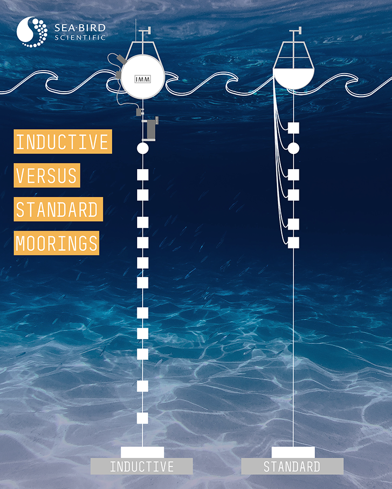
A buoy, a jacketed wire rope, and some exposed metal. In its simplest form, that’s all you need to create an inductive modem (IM) mooring.
- The buoy supports the surface modem, power supply, and data logging/transmission. Some buoys may also contain weather sensors, or oceanographic instruments directly connected via RS-232.
- A plastic jacketed wire rope acts as both the mooring’s seafloor tether and the data transmission medium
- Exposed metal at the top and bottom of the tether grounds the loop to seawater, forming an inductive loop along the mooring cable.
Clamp up to 100 underwater IM sensors to the tether, and you’ve done away with dozens of cables and bulkhead connectors, cutting costs and creating a more flexible deployment platform.
Virtually all IM-enabled moorings have these characteristics in common, but the physical configuration may differ depending on the use case and deployment environment. With the right equipment and configuration, inductive modem telemetry powers systems ranging from open-ocean buoys to through-ice applications. Read on to learn about 5 different IM configurations.
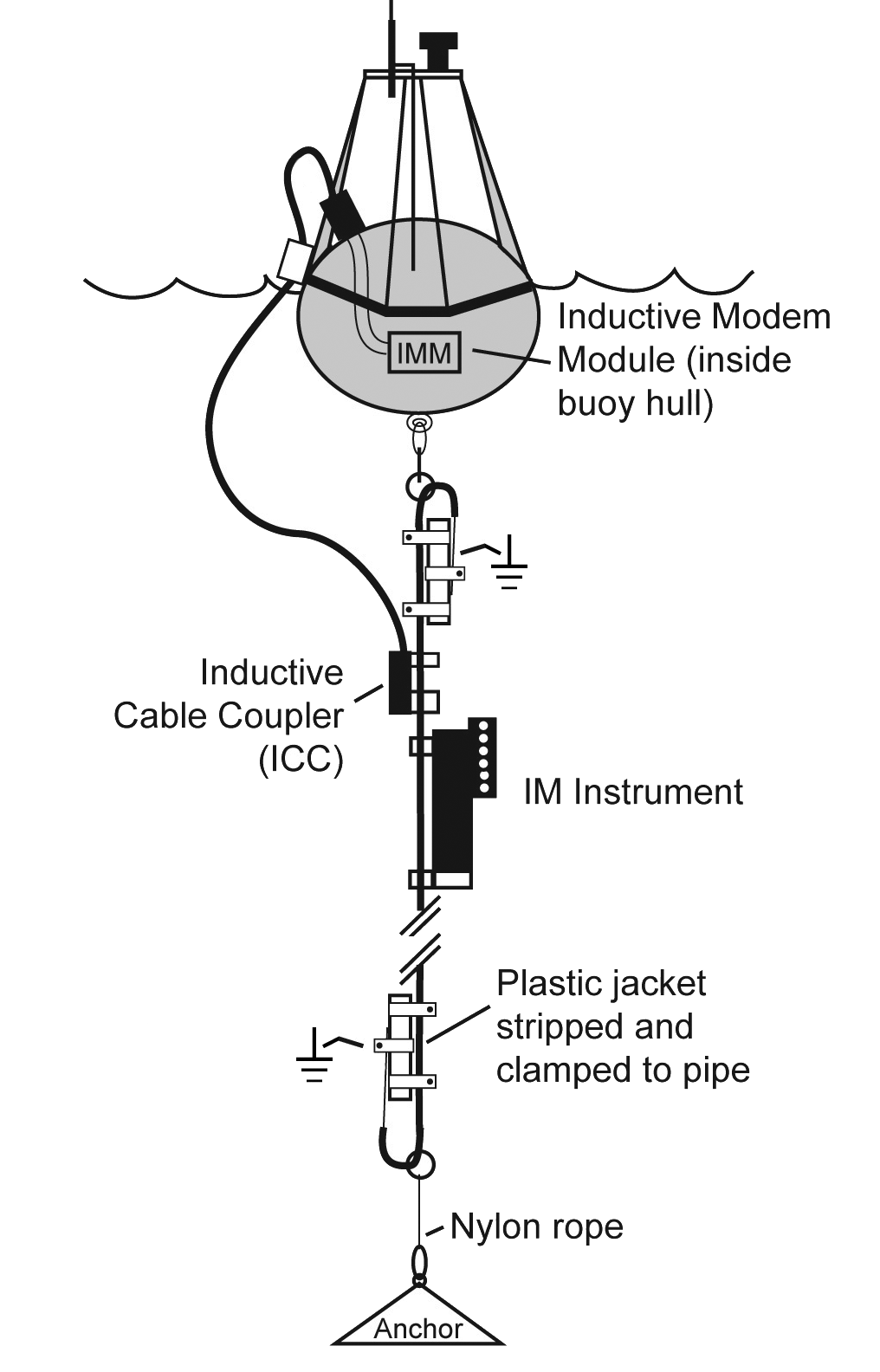
The Typical Inductive Mooring
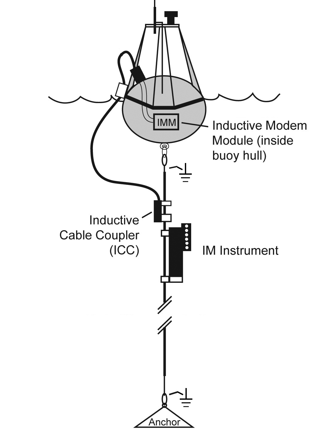
Most moorings in the ocean (both IM and non-IM) use a plastic-jacketed galvanized steel wire rope as the seafloor tether, as the plastic jacket provides corrosion resistance. The ends of the wire rope are terminated with steel thimbles or swaged eye terminals. This is easily converted to an IM system: the jacketed wire rope inherently supports IM communication, and the thimbles or eye terminals form an ideal seawater ground.
The surface buoy contains a controller that communicates via RS-232 to a Sea-Bird Scientific surface modem, either the Inductive Modem Module (IMM) or the Surface Inductive Modem (SIM). The surface modem converts the RS-232 signals to DPSK, send these commands via a through-hull bulkhead connector to the Sea-Bird Scientific Inductive Cable Coupler (ICC), which transmits this signal along the mooring line. As with the IM instruments, the ICC simply clamps anywhere along the plastic-jacketed portion of mooring cable. The underwater IM instruments receive this signal. They take a sample, return their data via the mooring cable, where it travels from the ICC, to the IMM, gets converted to RS-232, and is sent to the buoy controller for wireless transmission.
Individual inductive modem instruments may be clamped along this mooring cable at any position. Each instrument can be freely moved up or down the cable.
Direct Connection Mooring
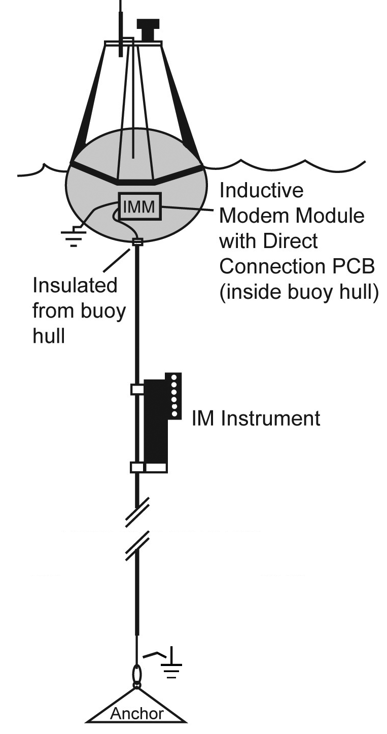
Similar to the typical mooring, but without the ICC and topside seawater ground. The mooring cable enters the hull of the buoy and forms a direct electrical connection to the surface modem (typically an IMM). A separate cable extends from the IMM to the outside of the buoy hull to form the topside seawater ground.
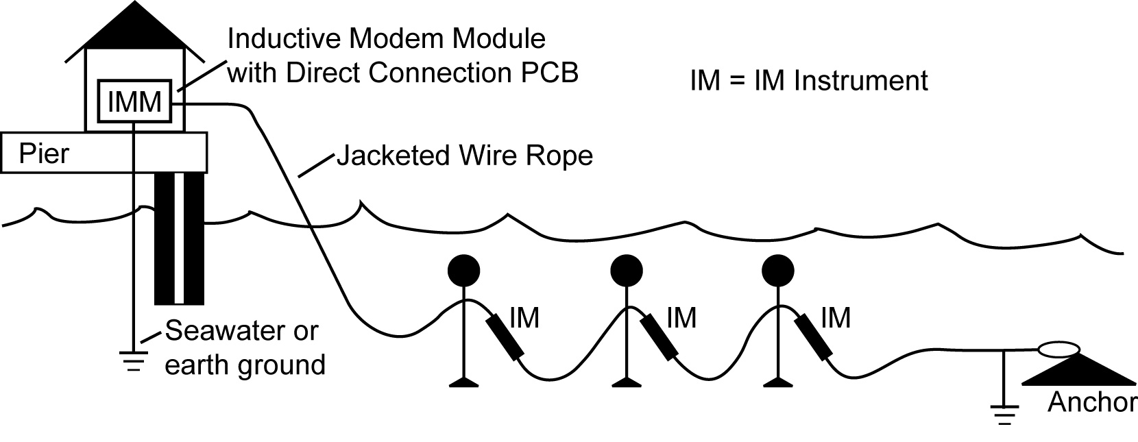
Cable-to-Shore Deployment
Useful for onshore deployments, this configuration supports moored instruments secured to a pier or the seafloor. Like the Direct Connection mooring, the jacketed wire rope is electrically connected to the surface IMM and a separate cable extends from the IMM to the seawater to form a seawater ground. Since the jacketed wire rope is not anchoring a buoy, it can be snaked across the seafloor for flexible placement of the underwater instruments.
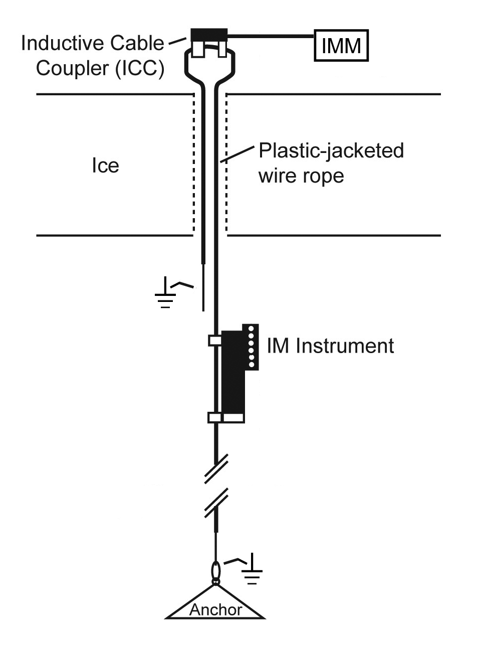
Through-Ice Deployment
The IMM and ICC sit atop the ice. One end of the jacketed wire passes through the ICC, through the ice, and terminates as bare metal to form the “topside” seawater ground. The other end of the jacketed wire is identical to the typical IM mooring – it passes through the ICC, through the ice, and down to an anchor, with IM instruments attached along the line.
Freshwater Mooring
Lower electrical conductivity in freshwater creates a weaker inductive loop. Unlike seawater, which can support mooring lengths of up to 7000 meters, freshwater deployments are limited to approximately 1000 meters before communication breaks down. To account for this lower conductivity, the underwater ground at the top and bottom requires more exposed metal.
Typical inductive moorings require a length of metal pipe (galvanized or stainless steel) at the top and bottom of the cable to account for lower conductivity.
For freshwater moorings simulating the direct connection design, connect the IMM ground to several square feet of unpainted surface on the buoy to form the topside ground.
Related Posts


Featured Posts
UG2 Workshop 2024
We hope to see you at UG2 '24 We are excited to sponsor the upcoming 2024 Glider Workshop in Ann Arbor, Michigan, from September 10 - 12, 2024. Overview This workshop will bring together the global underwater glider community to strengthen international collaboration...
Oceanology International 2024
We hope to see you at #Oi24 We are excited to return to Oceanology International 2024 again in London, UK from March 12-14. Overview Oceanology International brings together 500+ exhibitors in the only event that links the three key players in the industry:...
Ocean Sciences Meeting 2024
We hope to see you at #OSM24 We are excited to return to Ocean Sciences Meeting 2024 in New Orleans, Louisiana from February 18-23 at booth number #527. Overview The Ocean Sciences Meeting 2024 is co-sponsored by the American Geophysical Union, the Association for the...
Science and Technology
Platform