Inductive Modem Telemetry
Bulkhead connectors, the sole line of communication to countless sensors, are robust and sturdy. They have to be – we place a lot of faith in their ability to exclude corrosive seawater and support a steady flow of electricity. And while tens of thousands of instruments are currently chattering away through XSG and MCBH connectors, the fact remains: the ocean is a hostile environment for the humble electrical connector.
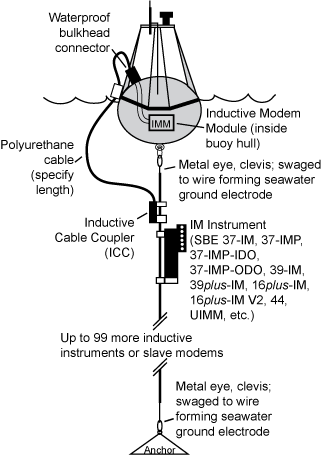
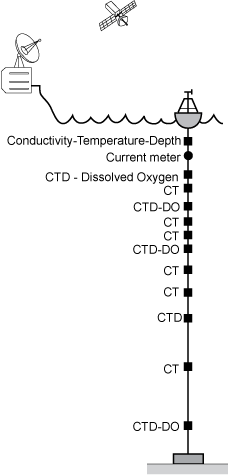
Enter Sea-Bird Scientific’s Inductive Modem (IM) system. IM systems eliminate the need for connectors entirely, transforming a mooring’s tether into a medium for real-time data transmission. While traditional real-time moorings relied on failure-prone breakout cables, IM systems do not require a direct electrical connection to each underwater instrument. Up to 100 instruments can be positioned at any depth along the mooring line and still communicate in real-time. Several instruments are designed for IM telemetry, but non-IM biogeochemical and third-party sensors can be adapted for use on an inductive modem mooring.
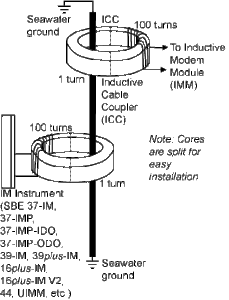 An Inductive Modem Module (IMM) uses electrical current loops to transmit information; current flowing in a wire loop induces current to flow in a loop that passes through it. In Sea-Bird’s IM system:
- The first loop is formed by the coupler connection of the surface buoy to the mooring cable.
- The second loop is formed by the mooring cable and the seawater; the cable is bare metal on the top and bottom and insulated in the middle.
- The third loop is at each underwater instrument.
Because all coupling is done in loops, no cable breakouts are required.
For those familiar with the SBE 911plus CTD system, IM systems use the same type of telemetry for data transmission. Just as the 9plus CTD transmits real-time data via a 10,000 meter load-bearing sea cable, IM systems transmit their data via the mooring line. This is known as the Differential Phase Shift Keying (DPSK) technique.
For typical saltwater applications, the maximum transmission length is approximately 6,000 meters. In fresh water, with its lower conductivity, good communications can be obtained over 1,000 meters.
A Typical Inductive Mooring
A typical mooring in the ocean uses a plastic-jacketed galvanized steel wire rope. This cable is frequently used for non-inductive oceanographic moorings because of the corrosion resistance provided by the plastic jacket. The ends of the wire rope are terminated with steel thimbles or swaged eye terminals. Deep moorings typically employ synthetic line below the lowest instrument.
Individual inductive modem instruments may be clamped along this mooring cable at any position. Each instrument can be freely moved up or down the cable.
The surface buoy contains a controller that communicates via RS-232 to a Sea-Bird Scientific Inductive Modem Module (IMM). The IMM converts the RS-232 signals to DPSK, send these commands via a through-hull bulkhead connector to the Sea-Bird Scientific Inductive Cable Coupler (ICC), which transmits this signal along the mooring line. As with the IM instruments, the ICC simply clamps anywhere along the plastic-jacketed portion of mooring cable. The underwater IM instruments receive this signal. They take a sample, return their data via the mooring cable, where it travels from the ICC, to the IMM, gets converted to RS-232, and is sent to the buoy controller for wireless transmission.
Related Posts
Featured Posts
UG2 Workshop 2024
We hope to see you at UG2 '24 We are excited to sponsor the upcoming 2024 Glider Workshop in Ann Arbor, Michigan, from September 10 - 12, 2024. Overview This workshop will bring together the global underwater glider community to strengthen international collaboration...
Oceanology International 2024
We hope to see you at #Oi24 We are excited to return to Oceanology International 2024 again in London, UK from March 12-14. Overview Oceanology International brings together 500+ exhibitors in the only event that links the three key players in the industry:...
Ocean Sciences Meeting 2024
We hope to see you at #OSM24 We are excited to return to Ocean Sciences Meeting 2024 in New Orleans, Louisiana from February 18-23 at booth number #527. Overview The Ocean Sciences Meeting 2024 is co-sponsored by the American Geophysical Union, the Association for the...
Science and Technology
Platform
