Analog Sensor Integration Guide
From bottom contact triggers to transmissometers, oceanographic sensor options are vast and diverse, and choosing the right combination of sensors can significantly augment a CTD’s measurement capabilities. Although getting disparate technologies to talk to one another is typically a difficult process, many of these sensors have a simple 0-5 V analog output, making the integration process much more seamless.
What Are Analog Voltage Sensors?
The 0 – 5 V signal is an analog representation of the sensor’s measurement, to be converted to engineering units in post-processing. Consider the following profile:
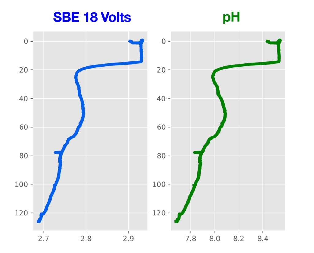
The SBE 18 is an analog-output pH sensor with an electrode that responds to pH in seawater and outputs a voltage that corresponds with this measurement. The profile on the left shows the voltage output from this sensor, while the profile on the right shows the converted pH values. Because there is a linear relationship between raw voltage and converted pH, the shape of each profile is similar.
pH = 7 + (V – offset) / (°K * 1.98416e-4 * slope)
where
V = voltage output from the SBE 18
offset = calibration coefficient
slope = calibration coefficient
°K = temperature in degrees Kelvin
This calculation is not done by the CTD – the CTD only records the SBE 18’s voltage output, which must then be converted in post-processing. The software applies this conversion formula to the raw voltage logged by the CTD. To make this conversion, it needs an .xmlcon configuration file that includes the calibration coefficients (“slope” and “offset”) for the SBE 18 sensor.
Of the Sea-Bird Scientific CTDs, five models can support analog auxiliary sensors: the 9plus, 25plus, 19plus V2, 16plus V2, and the SBE 21 Thermosalinograph. When equipped with a collection of auxiliary sensors, these CTDs can become self-contained research platforms, providing power, aligning sample timing, facilitating data logging/transmission, and even integrating sensors into the CTD’s pumped flow path. The configuration process will differ by each CTD, but the underlying concepts are the same.
Physically connecting a sensor to the CTD
There are 2 major considerations to make before connecting a sensor to a CTD:
- Selecting the right cable
- Which of the CTD’s connectors to plug the cable into
When connected and configured, the CTD will do two things: provide power to the auxiliary sensor, and log/transmit that sensor’s 0-5 V signal. It is critical to use the correct cable to connect the sensor to the CTD; just because a given cable has the right connectors does not mean that the cable’s internal leads are correct. Using the incorrect cable can damage a sensor.
Identifying the Cable
Sea-Bird provides the Cable Search tool on our website, which allows users to identify the proper cable for a given CTD and sensor, and access drawings of the cable to confirm.
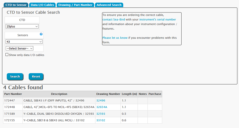
Learn how to use Cable Search here.
Identifying the CTD Connector
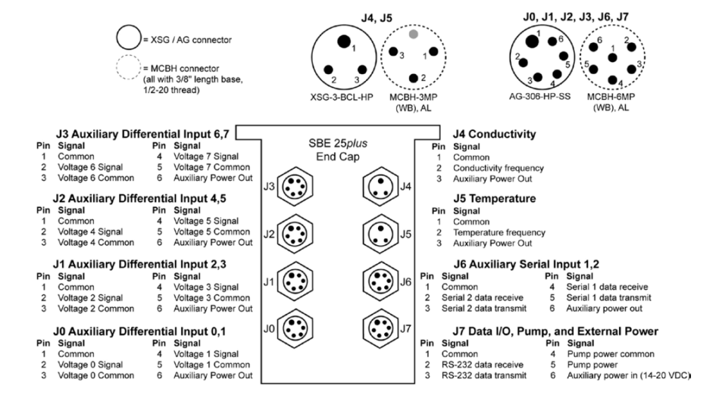
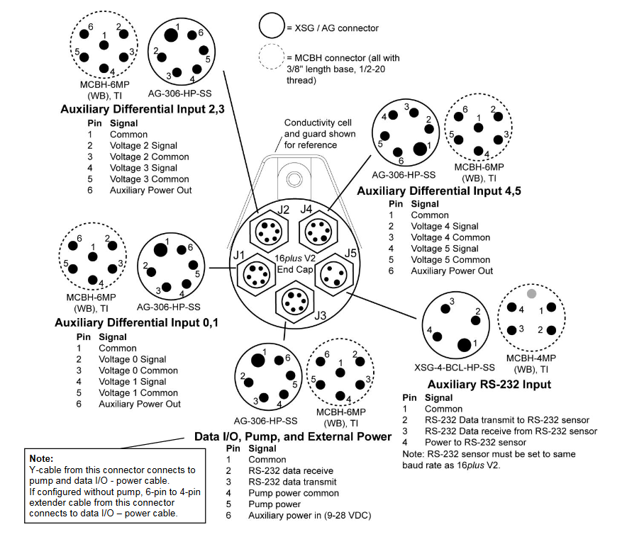
Sea-Bird CTDs that support auxiliary sensors have several connectors, and it is crucial to select the correct one (this also has implications for creating the .xmlcon configuration file). Note the connector diagram for a 19plus V2 below:
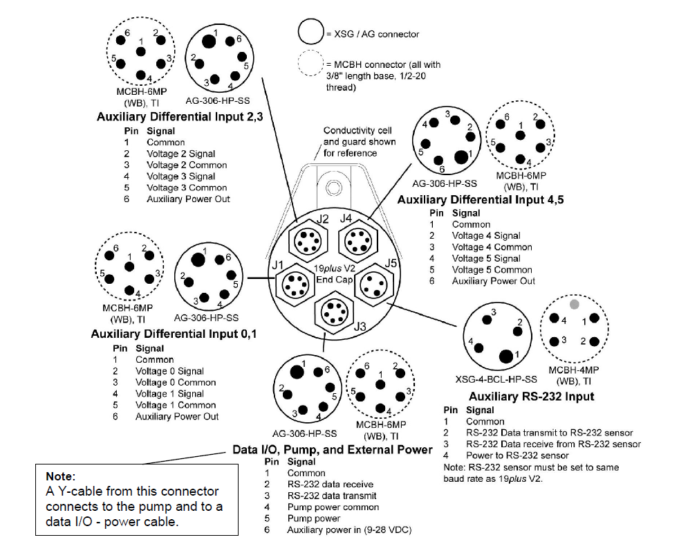
Connectors J1, J2, and J4 labeled “Auxiliary Differential Input” are for supporting analog-output sensors. Each connector has two voltage channels and power output, meaning it can support two auxiliary voltage sensors. Refer to the connector diagram before plugging a cable into the CTD.
9plus Connector Diagram
25plus Connector Diagram
19plus V2 Connector Diagram
16plus V2 Connector Diagram
Cross-Referencing the Cable Drawing to the Connector Diagram
If you have the cable drawing and the connector diagram, you can identify which of the CTD’s voltage channels will accept data from the auxiliary sensor and verify that your cable is correct. This is particularly important when using a Y-cable, which connects two auxiliary sensors to a single CTD connector.
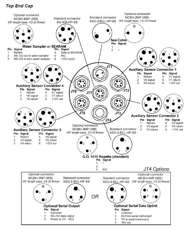
The diagram below illustrates how to identify which voltage channel each sensor will connect to when plugging a Y-cable into connector J1 on a 19plus V2:
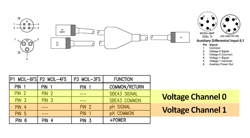
The SBE 43 connects to pins 2 and 3 on the CTD, which correspond with “Voltage 0 Signal/Common” (e.g. Voltage Channel 0) on the connector diagram. The SBE 18 connects to pins 4 and 5 on the CTD, which correspond with “Voltage 1 Signal/Common” (e.g. Voltage Channel 0).
Creating a Configuration File
Once the sensors are physically connected to the CTD, the next step is to create or modify the CTD’s .xmlcon configuration file. This file tells Seasave or SBE Data Processing how to convert the analog voltage from any auxiliary sensors to engineering units. Any changes to the CTD configuration will necessitate a change to the configuration file, or the software will fail to process the data correctly.
Configuration Files require a few changes when changing auxiliary sensors:
Sensor Order
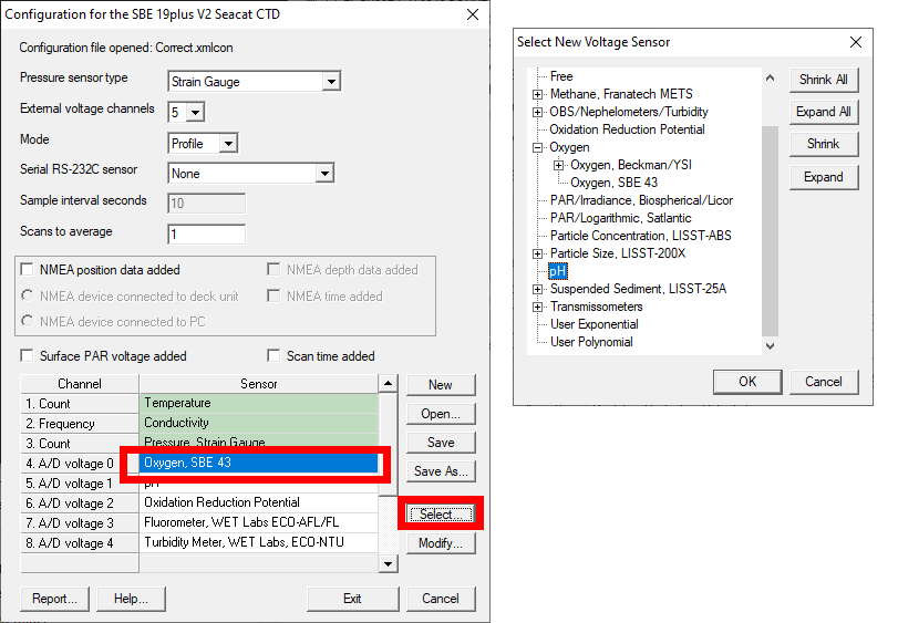
The order in which sensors appear in the configuration file must match the order that sensors are physically connected to the CTD. Note: for the 19plus V2, 16plus V2, and real-time output on the 25plus, voltage channels must be activated prior to logging data. Refer to the instrument manual for more information.

In the .xmlcon file above, the order of sensors listed matches the order of sensors connected to and activated in the 19plus V2 CTD. Note that CTD Voltage Channel 1 is not show in the list on the right– this is because no sensors have been connected to that channel (pins 4 and 5 on connector JT1). Despite this, the .xmlcon file is still correct, as the order of sensors in the .xmlcon file matches the order of sensors plugged into the CTD.
Sensor type
The sensors defined in the .xmlcon file must match the actual sensor used. To change the type, click on an A/D Voltage channel and slick on “Select”, then select the appropriate sensor from the list. If the particular sensor is not available, use the “User Polynomial” or “User Exponential” option, ensuring that the order of sensors is correct as shown above.
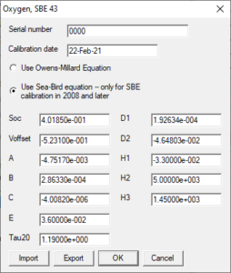
Calibration Coefficients
Coefficients in the .xmlcon file for each sensor type must match the calibration data from the most recent calibration. Double click on the sensor in the .xmlcon file and verify/change the coefficients.
Related Posts


Featured Posts
UG2 Workshop 2024
We hope to see you at UG2 '24 We are excited to sponsor the upcoming 2024 Glider Workshop in Ann Arbor, Michigan, from September 10 - 12, 2024. Overview This workshop will bring together the global underwater glider community to strengthen international collaboration...
Oceanology International 2024
We hope to see you at #Oi24 We are excited to return to Oceanology International 2024 again in London, UK from March 12-14. Overview Oceanology International brings together 500+ exhibitors in the only event that links the three key players in the industry:...
Ocean Sciences Meeting 2024
We hope to see you at #OSM24 We are excited to return to Ocean Sciences Meeting 2024 in New Orleans, Louisiana from February 18-23 at booth number #527. Overview The Ocean Sciences Meeting 2024 is co-sponsored by the American Geophysical Union, the Association for the...
Science and Technology
Platform